ECU V3SMD
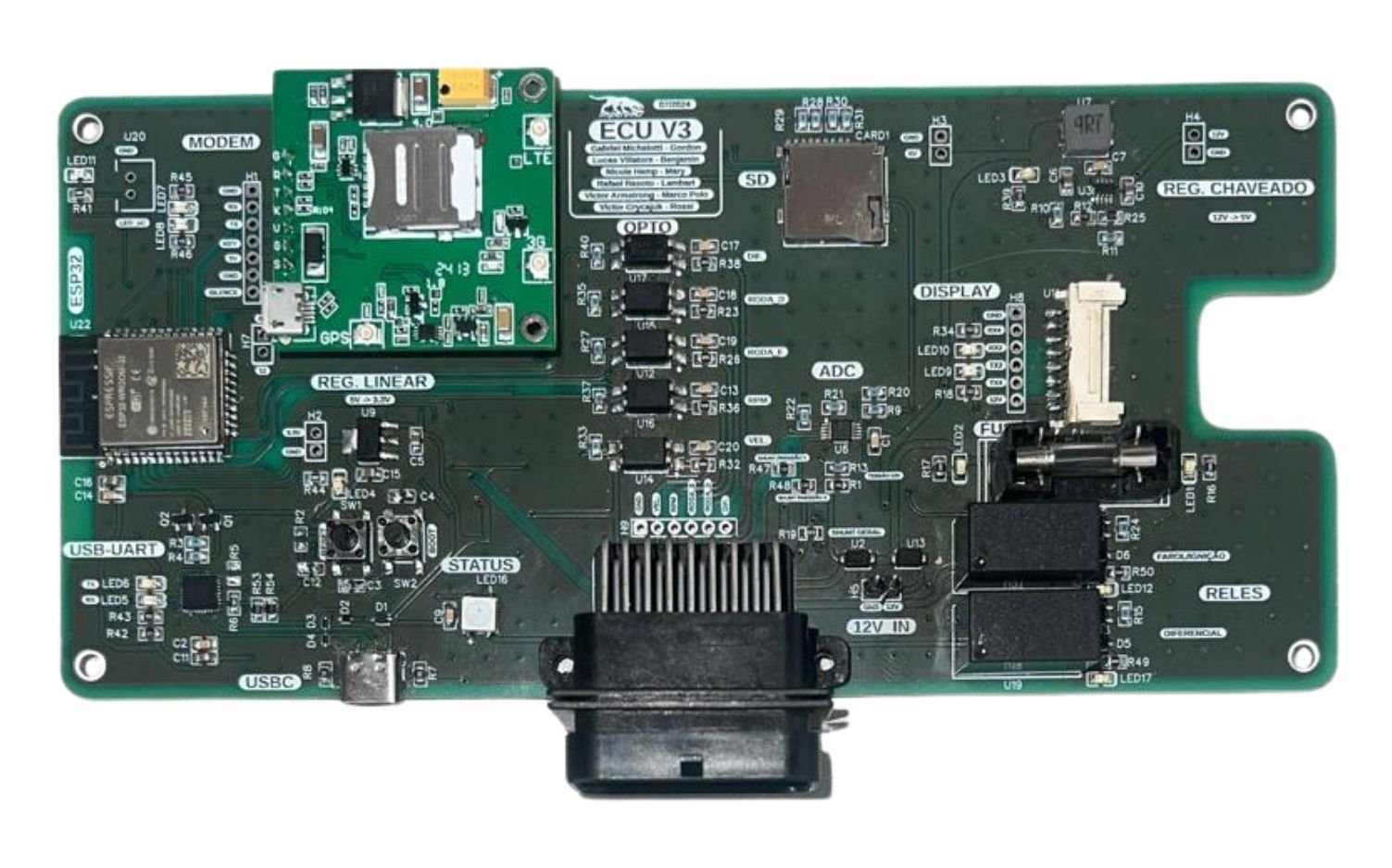
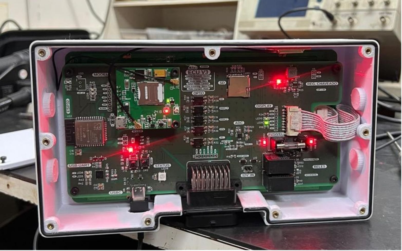
The third generation of the Equipe Imperador ECU, the one that moved to SMD components and merged the separate modules onto a single board. My last piece of work for the team.
- 2024
- Hardware development lead
- Equipe Imperador · UTFPR
- Hardware · PCB · C++ · ECU
This was my last piece of work at Equipe Imperador. After a year and four months as Head of Electronics, I returned to the electronics team as a member to lead the hardware development for the next generation of ECUs, the car’s electronic control unit.
What the board does
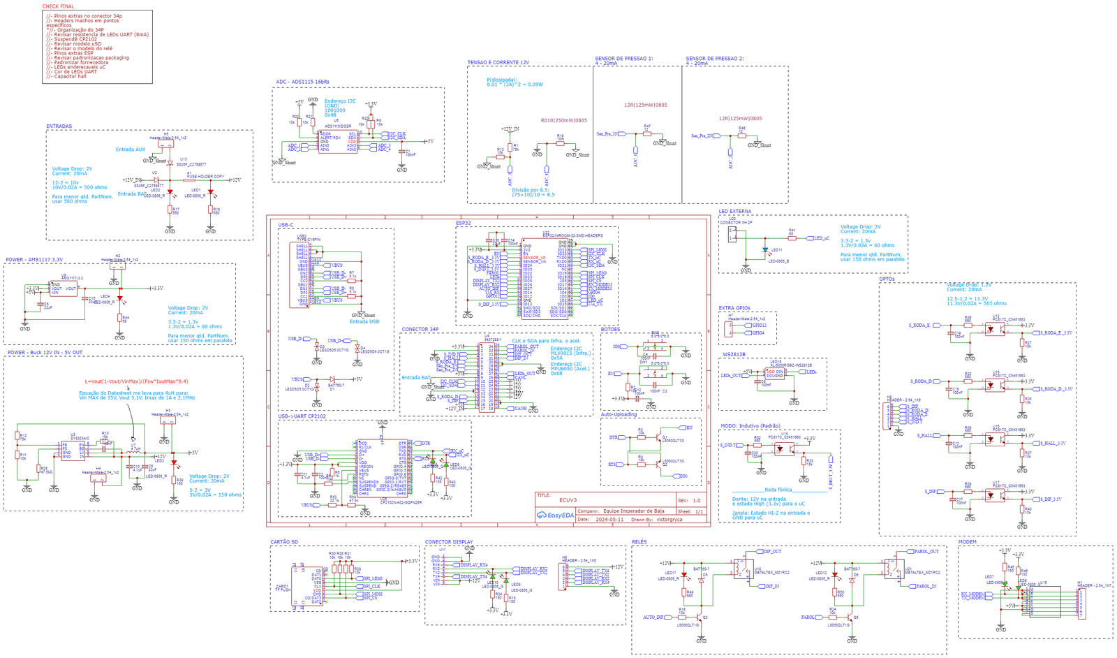
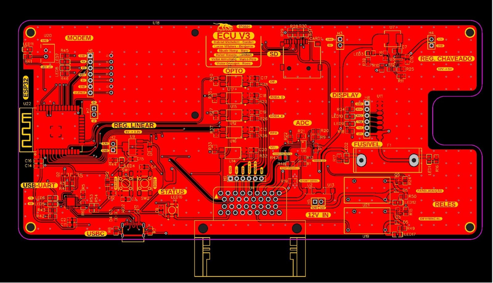
The microcontroller is an ESP32-WROOM-32, and everything that connects to the car goes through a single 34-pin connector.
On the input side, the board reads both wheels, the hall sensor and the differential through tone-wheel inputs isolated by optocouplers; two pressure sensors on a 4 to 20 mA loop; and the voltage and current of the 12 V system, current measured across a shunt. The analog readings go through a 16-bit ADS1115 rather than the ESP32’s own converter. An I2C bus leaves on the same connector, for the infrared thermometer and the accelerometer.
On the output side, two relays drive the differential lock and the headlight.
Data leaves by three paths. An SD card for onboard logging, one serial line to the driver’s display and another to the modem. The CAN bus is on the 34-pin connector too.
Power comes from the car’s 12 V, with a switching regulator for 5 V and a linear one for 3.3 V. Programming is over USB-C, with a CP2102 bridging USB to serial and the auto-reset circuit that removes the need to press a button to flash firmware.
Outcome
The hardware worked. The software side is under continuous improvement by the team.
The repository
The project has a public repository at github.com/VictorGryca/BajaECU, which is where the files and anything else published about the board live.
3D model
The ECU board, exported from CAD.
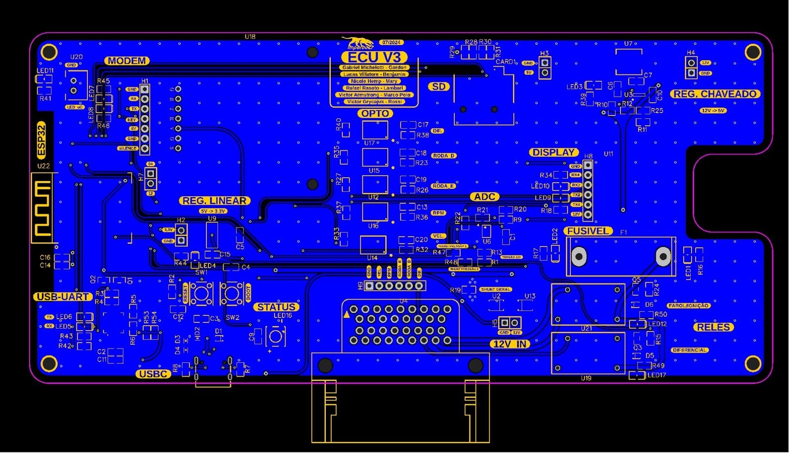
PCB layers
Visual record